
Range of Experiments
1. Verification of the elastic torsion equation.
2. Determination of modulus of rigidity and yield shear stress.
3. Determination of upper and lower yield stresses for normalized steel specimens.
4. Investigation of the behavior of materials under plastic deformation and the phenomenon of work hardening.
5. Determination of modulus of rupture in torsion.
6. Reversed torsion tests to demonstrate the Bauschinger effect and the effects of residual body and textural stresses on torsional strength.
7. If heat treatment facilities are available a wide range of tests can be carried out to demonstrate the effect of heat treatment on residual stresses and torsional strength.
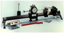
Description
The SM1 MkII Torsion Testing Machine has the same basic features as its well known predecessor but has been improved by introducing a digital torque measurement system and extending the length of the unit to allow tests on longer specimens if required. A rigid square aluminum tube is supported at each end by cast aluminum feet and carries a straining head at one end and a torque measuring system at the other. The straining head consists of a 60:1 worm drive reduction gear box mounted on a special extruded aluminum platform which slides long the square tube and can be locked in any position. The output shaft is free to slide on a keyway in the gear box to accommodate any change in length of the specimen during testing and to enable insertion of specimens. Reaction to the torque applied to the specimen is supplied by the torsion shaft which is supported at each end by self aligning bearings. Test specimens are held at each end by hexagonal drive sockets which fit on the gearbox output and torsion shafts. An arm is fitted to each end of the torsion shaft, the one at the far end being located by a turnbuckle and hand wheel for adjusting the angular position of the torsion shaft. The arm at the inner end bears on a dial gauge and can be adjusted using the turnbuckle to maintain one end of the specimen in a fixed position during tests. A linear potentiometer is fitted between the two arms and provides an output proportional to the angle of twist of the torsion shaft.
The potentiometer is connected to a digital meter which reads directly in Nm and lbf in. A calibration arm, weight hanger and weights are supplied for checking or recalibrating the meter if required. Strain of the specimen is measured by protractor scales on the gearbox input and output shafts, these scales being locked in position by knurled thumbnuts. A resettable digital revolution counter is also fitted to the gearbox input shaft to provide a record of total input revolutions in any test. Measurements of specimen strain can be obtained when the torsion shaft is adjusted during a test to maintain one end of the specimen in a fixed position. A Torsiometer, SM2, can be supplied as an extra, if required, for greater accuracy in measuring strain, for example, in determining modulus of rigidity.
Specification
Nominal Capacity: 30Nm (300 lbf in)
Gearbox Ratio: 60:1
Torque meter:
TQ E101 digital Torque measuring system with 3 1/2 digit display and Nm and lbf in changeover switch (supplied as standard with each SM1 MkII apparatus).
Calibration arm: 500mm (20in) long.
Calibration weights: 2 off 2kg, 1 off 1 kg 1 off 500g with 500g weight hanger.
Extras:
SM2 Torsiometer: Mechanical Torsiometer for use with 6mm diameter specimens in both the elastic and plastic regions.