
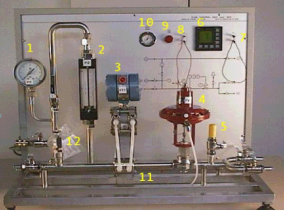
- Bourdon spring pressure gauge, range 0-6 bar
- Variable area flow meter, range 100-1000 l/h
- . Electronic differential pressure transmitter, range 0-1000 l/h of water and 30 Nm3/h of air
- Pneumatic control valve
- Silencer in plastic material
- Microprocessor controller
- 2measurement terminals for the 4-20 mA output signal of the controller
- 2measurement terminals for the 4-20 mA input signal of the controller
- Power supply light
- Pressure gauge, 0 - 2.5 bar
- Calibrated diaphragm
- Safety valve
Description of apparatus:
The unit Mod. FCB/EV can be used to study the automatic flow-rate control through the typical system composed of calibrated diaphragm, control valve, differential pressure transmitter and PID controller. The process fluid can be water or air. The system is provided with a specific supervision software, mod. SW – FCB/EV, that provides the P.C. control. The bench can be connected in series with Mod. PCB/EV or in parallel to the other automatic control units (Mod. LCB/EV and TCB/EV). FCB/EV.
Experiments done on it:This unit used to control the flow rate of fluid.
The operating principle of the equipment can be described as follows. The fluid, crossing the calibrated diaphragm, causes a pressure drop proportional to the flow rate.
The electronic transmitter FT1 measures the pressure drop Δp (in mmH2O), extracts the square root of the measured value, and sends the 5 PID electronic controller a 4-20 mA electrical signal proportional to √Δp and so to the flow rate.
The signal sent by the transmitter FT1 to the PID controller is compared to the set point value set on the controller. At this point, the controller sends the output a signal, function (PID) of the shift between the value of the process variable and the set point. This electrical signal is converted by an electropneumatic converter into a pneumatic signal controlling the valve opening degree.
The signal at the input and output of the PID controller can be measured with a milliammeter using the proper terminals set on the board. The output signal to the I/P converter can be read directly on the pressure gauge set on the board. The controller is pre-set to PI mode (proportional + integral) as the derivative action is not generally used in the flow rate control.